Project Methodology
Aerial Photography
When one thinks about what archaeologists typically do, digging underground immediately comes to mind. But the Theban Mapping Project has found that going up, in airplanes and hot air balloons, can provide equally valuable archaeological data.
Airplane Photography
In 1979, after several months of discussion and negotiation, the Theban Mapping Project signed a contract with the Remote Sensing Center of the Egyptian Academy of Scientific Research under which the Center would provide complete aerial photographic coverage of the Theban Necropolis and areas immediately adjacent. The area covered included over 60 square kilometers (23 square miles). All equipment and supplies, as well as the specifications of the flights themselves, were governed by standards for aerial photographic work set forth by the State of California, standards that equaled or exceeded those of other American and international government and research agencies.
Two scales of aerial photography were required for the desired photogrammetric mapping. For the general mapping of all the Necropolis, five flight lines were photographed at 1,700 meters (5,577 feet) (+ or -) above sea level elevation. For one-meter contour interval mapping, this results in a "C-factor" (a limiting factor) of 1,600 meters (5,250 feet) (+ or -). The larger scale mapping of areas of intense archaeological interest required nine flight lines at 900 meters (2,953 feet) (+ or -) above sea level elevation. The C-factor for this photography is an optimum value of 850 for one-meter contour-interval mapping. We also flew flights at 1,100 meters (3,609 feet). For the ground control of all fourteen flight lines, 47 of the transverse control points were pre-targeted.
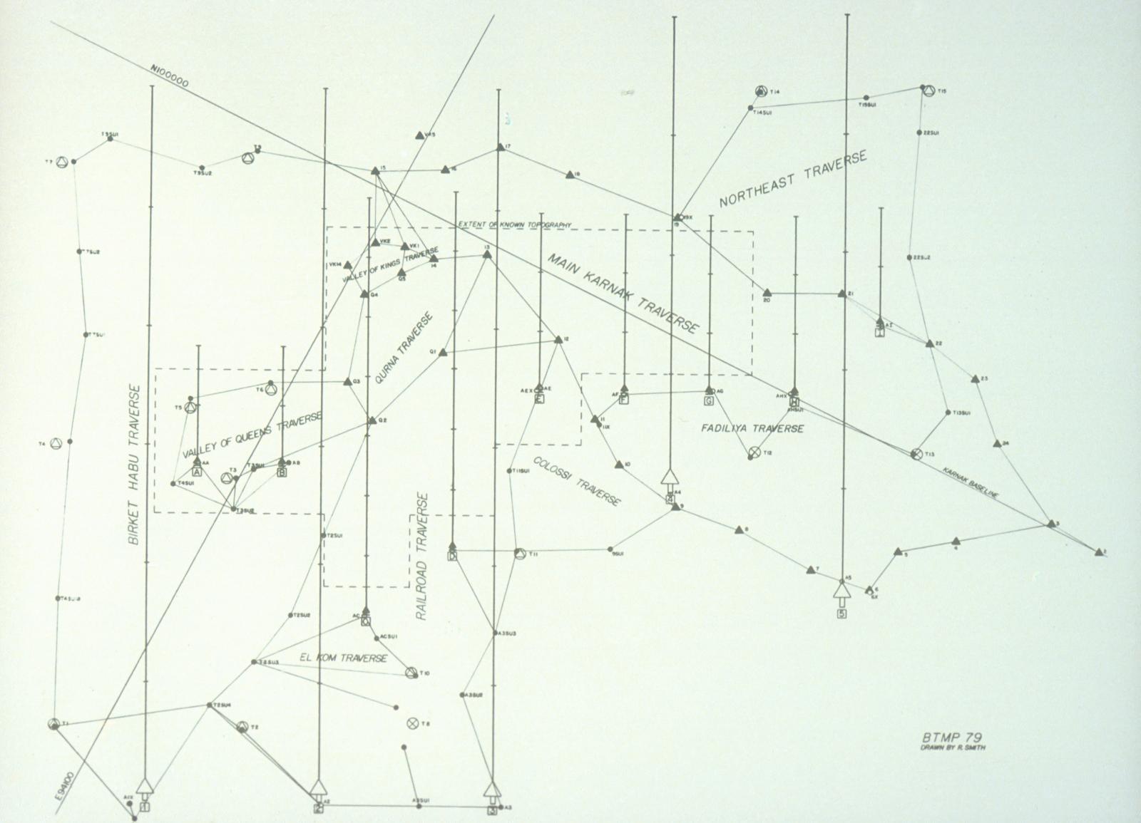
The analytical control method that was used in the photogrammetric mapping does not require that many "picture" points. However, the additional points were targeted to provide the aerial photographic team with orientation marks and check points in areas where there was no existing mapping that could be used as flight guides. In addition, the beginning of all fourteen flight lines were pre-marked for further guidance of the flight crew. Flights were run twice, mid-afternoon, in spring 1979.
A section of this image, focusing on the area of the ancient monuments, is now available in a zoomable format in our new Atlas of the Theban Necropolis. It was prepared by TMP photographer Francis Dzikowski, who montaged together fourteen 9x9 inch (23x23 cm) diapositives in Photoshop.
Hot-Air Balloon Photography
The use of hot-air balloons for archaeological surveying is by no means a new technique, but it was one that had not been used in Egypt until the 1982 season of the Theban Mapping Project. Our reasons for wishing to make use of balloons for aerial photography were simple. We hoped to obtain low-level oblique photographs, and at the same time, to explore the numerous wadis and cliff faces in the Theban Necropolis for archaeological features that had not yet been noted. Such photographs are of particular usefulness for the study of architectural details, small-scale landforms, and for the plotting of unexcavated archaeological remains, which are nevertheless visible from low-level flights.
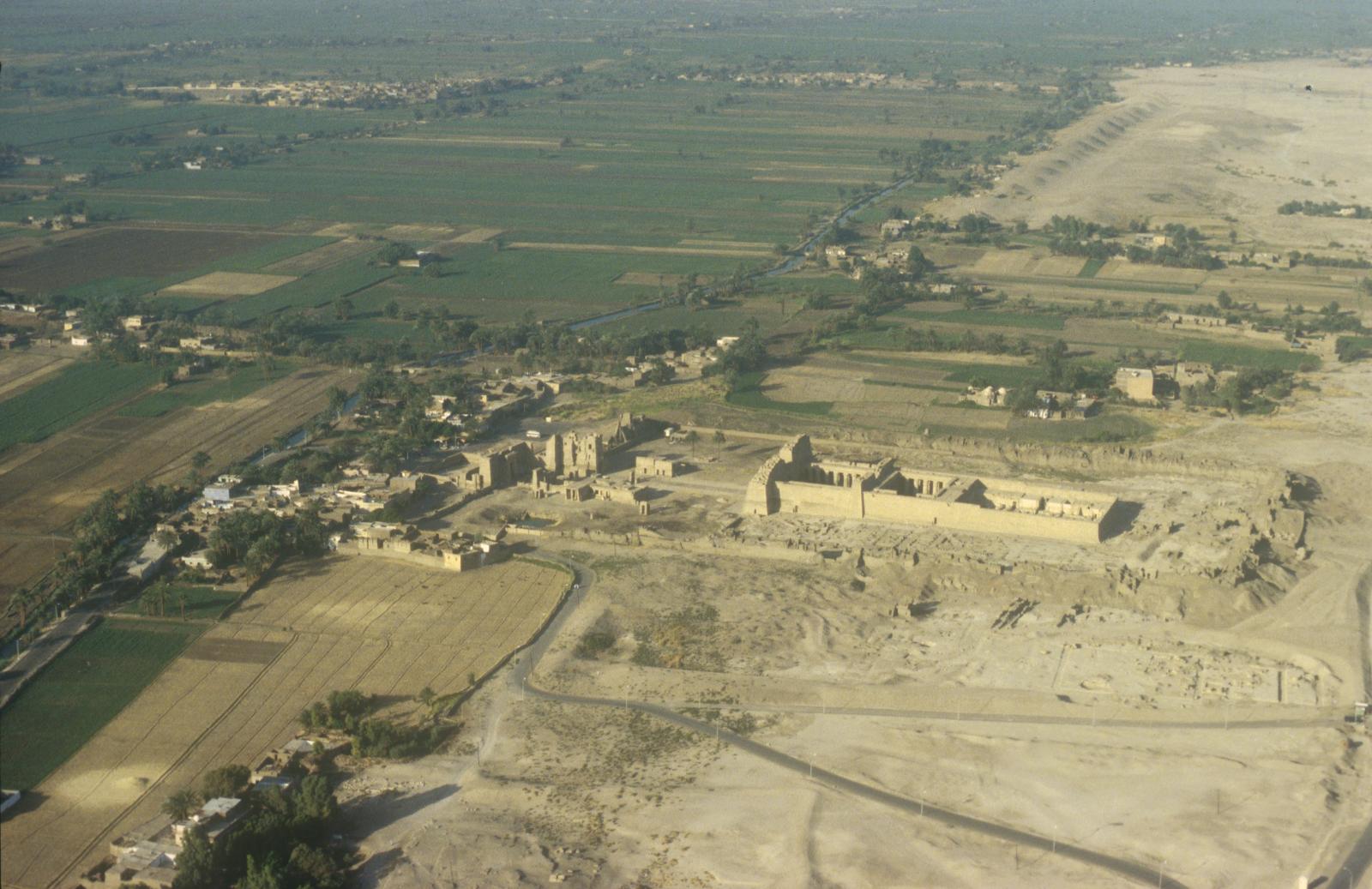
A balloon was the perfect vehicle for such work: it is able to fly very slowly, at very low altitudes, and provides a perfectly stable photographic platform. It also is inexpensive, burning only local Egyptian butane as fuel. Flights, depending upon the areas or monuments to be photographed, might be at altitudes of as little as 3-4 meters (9-13 feet), or as much as 500 meters (1,640 feet). Speed, dependent on the wind, is rarely greater than 1-2 kilometers (.6-1.2 miles) per hour.
In May 1982, two balloons were chartered from a firm in Napa, California and brought to Egypt by the TMP. The flights proved so successful that the TMP purchased one of these balloons for continued aerial photography in the following season.
The TMP no longer owns its own balloon, but the balloons proved to be such a hit that several companies offering balloon flights over Luxor for tourists have since been established, and the TMP continued to use their services for obtaining more aerial photography in the subsequent decades.
The opportunity to obtain bird's-eye views of the Theban Necropolis resulted in the discovery of several interesting features. Indeed, one of the more intriguing aspects of the aerial work in the first season was the discovery of an archaeological feature that probably would not have been seen had we not had the balloons available.
During one of our flights in 1982, our balloon was blown slightly northward of its intended flight plan, over the Thoth Temple at the northernmost end of the Theban Necropolis. As the balloon descended, the crew noticed a rectangular hole in the cliff of a small spit of the Wadi ar-Rumalla. The location of this opening led us to suspect that this might be a cliff tomb similar to those queens' tombs of the New Kingdom. We marked the tomb entrance at the top of the cliff, and a few days later, surveyed its precise grid and made plans to explore its interior. This was accomplished by several team members who were experienced rock climbers, who rappelled into the "tomb" from the cliff face above. Inside, they discovered that all of the evidence suggested that the chambers actually served as a Christian hermitage, possibly dating to the seventh century A.D.
All of the photographs obtained by the Theban Mapping Project showed temples and hillsides from angles that had never seen before.
(Excerpted and adapted from The Berkeley Map of the Theban Necropolis: Report of the Second Season, 1979 and The Berkeley Map of the Theban Necropolis: Report of the Fifth Season, 1982.)
Drawings
The plans and sections of the individual tombs available on this website were drawn using Graphisoft ArchiCAD software from survey field notes. Set-up points (SUs) and reference lines were first set down. Radiating lines representing the azimuth and zenith angles and slope distances to tomb features were extended from each SU; these lines were then joined to complete the drawings. In the case of a tomb surveyed using a Total Station, the features of the tomb were automatically resolved into X, Y, and Z coordinates by the total station, and those coordinates were used to generate the plan and sections.
In the case of tombs not surveyed by the Theban Mapping Project (i.e. not accessible during the TMP's field seasons of 1979-89), published and unpublished plans from other researchers were used as the basis of the CAD drawings. An image would be scanned, and then imported into ArchiCAD, where it was resized to the correct scale. This raster image was then traced by hand. In general, each tomb is available in plan, accompanied by at least one (longitudinal) section if possible. More sections are given if there are significant differences between the right and left longitudinal sections, or if transverse sections are required to clearly show the architectural features of the tomb. Where two or more tombs overlap, the section through the main tomb also cuts through the adjacent tomb (or tombs) to show how they are spatially related.
For royal and other major tombs, an axonometric drawing is also given. This was generated from a 3-dimensional computer model of the tomb. Using the plan and sections, the model was built in ArchiCAD using walls, floors, and ceilings of 0.1 mm thickness. This gave a solid model that could be used to produce both shaded and wireframe views. Walls and ceilings are omitted or made "transparent" where necessary for clarity.
The topographic maps of the Valley of the Kings and the West Valley are based on those published by Cerný et al. in Graffiti de la montagne thébaine I: Cartographie et étude topographique illustré (1969-1970). The contours of the latter were first digitized by hand using AutoDesk AutoCAD software and correlated with the Theban Mapping Project Grid. The contours were then exported to ArchiCAD and combined with the plans of the individual tombs. For publication, all the drawings were exported out of ArchiCAD as EPS files and imported into Adobe Illustrator. In Illustrator the line-weights, line-types, tones, type fonts, etc., were set.
Drawing Conventions
Standard cartographic and architectural drawing conventions are used in the maps, with some additional conventions, as outlined below.
Topographic Maps
- Line Weight: The outlines of tombs are shown as thick lines (1), while interior features are shown as medium lines (2).
- Contour Interval and Contour Lines: Every fifth contour is shown in a heavier and darker line (3), while elevations are given at selected areas of the map (4).
- Grid Coordinates and Survey Monuments: The northing and easting coordinates (relative to the TMP Grid) are given at the border of each map (5). Extant survey monuments used by the TMP are shown as circles with cross-hairs within a black triangle, with their TMP grid coordinates and elevation indicated (6).
Tomb Drawings: Plans and Sections
- Line Weight: The outlines of tombs are shown as a thick line (1), while interior features are shown as a medium line (2).In plan, door-swings are shown as a thin line where there are clear indications of door sockets in the floor or ceiling (7); otherwise they are shown as a dashed thin line (8), for instance where there are slots presumably cut for a wooden lintel beam.In plan, the shape of vaulted ceilings is indicated as a thin line (9).In plan, where other tombs overlap or intersect the current tomb, they are shown as a thin line (10).In section, those parts of the other tombs cut by the section plane are shown, with a dotted line to emphasize the spatial relationship between the tombs (11).
- Line Type: In plan, features above the plane of the plan (e.g., a change in ceiling level) are shown in medium dashed line (12). In plan, the parts of a tomb believed to exist but not yet excavated are shown in thick dotted line (13).
- Grid Coordinates and Survey Set-Ups: The initial survey set-up (SU) at the entrance of a tomb is marked by a circle with cross-hairs (14). Its TMP grid coordinates and elevation are indicated next to it. The orientation of the tomb axis (shown in dashed-dot line) is given in degrees, minutes, and seconds clockwise from true north.
- Chamber Designations: The letter designation of the individual tomb components is indicated within the component itself on the plans. Side chambers generally are designated in alphabetical order starting from the left as one enters the main chamber and proceeding clockwise. Pillar numbers are indicated inside the pillars and are numbered from front to back and then left to right. The components and pillars in KV 5 do not follow this rule: chambers and pillars in this tomb are numbered according to the order in which they have been excavated. For KV 62, the tomb of Tutankhamen, Howard Carter's chamber designations are also given in parentheses.
- Section Indicator: A reduced-scale plan with a thick line representing the plane of the section cut is used to indicate the sectional view given. The two short lines at the end of the cut line point to the direction of view in plan.
Tomb Drawings: Axonometrics
- Line Weight: In general, a thick line is used for the axonometric drawings. A medium line is used to indicate the outlines of features that have been made "transparent" for clarity.
- Orientation: The direction of true north is also shown.
(Abridged and adapted from "Architectural and Topographic Drawings'' by Walton Chan; first published in Atlas of the Valley of the Kings, edited by Kent R. Weeks.)
Methods of Tomb Survey
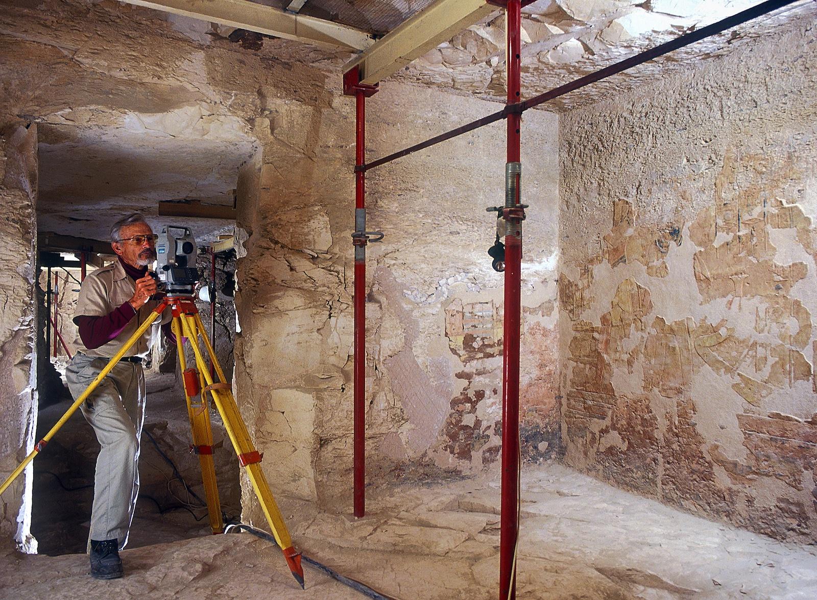
The Theban Mapping Project's tomb survey method uses a theodolite to measure the azimuths (horizontal angles), zeniths (vertical angles), and slope (direct) distances between the theodolite and the architectural features within a component. The features measured include corners, jambs, pillars, niches, and any other element deemed significant. A rough plan and section of the component is sketched and each feature to be surveyed is numbered on the. The measurements taken to each of these features are then lettered according to their vertical.
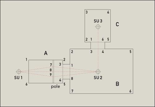
Following this method of notation, a measurement taken at the ceiling at corner 5 of chamber B would be designated B5a. If the corner appeared to be well cut and no intermediate measurements were considered necessary, the next measurement would be to the floor and would be designated B5e. All "a" measurements are to the ceiling, all "e" measurements are to the floor. The "e" azimuths and trigonometrically derived horizontal distances are those used in drawing the basic plan of the tomb.
The letters "b" through "d" may be used to describe intermediate measurements down a wall when these are needed to describe a vertical curve or irregularity. The letters "b" and "d" are also used at doorways: "b" to describe the top of a jamb when it meets a lintel rather than the ceiling; "d" to describe the bottom of a jamb when it meets a step rather than the floor. Letters "b," "c," and "d" are also used to designate recesses, niches and benches.
In a tomb where the walls of a chamber are irregular or where the ceiling is vaulted, extra measurements are taken along the walls or ceiling. The horizontal locations of these measurements are numbered on the plan and then lettered according to vertical position.
The survey begins in entryway A, where a control point was previously established. The theodolite is set up over the control point, the features of the entryway are measured and a new control point (or "set-up," abbreviated "SU") is established in the next chamber or corridor to be mapped. As far as possible, set-ups are located at 90, 180, or 270 degrees from the previous set-up (and zero degrees is set at the previous set-up). We have also found it useful to have at least two measurements overlapping from one set-up to the next. For example, the "a" measurement to jambs C1 and C6 would be measured from both SU 2 and SU 3. The overlapping measurements provide a quick check to catch mathematical and measuring errors.
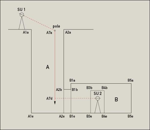
A slightly different method for setting inside control points must be used in shaft tombs, because of the impossibility of sighting into a tomb chamber from an outside control point at the edge of a shaft. From the initial set-up, we measure angles and distances to the upper edge of the shaft.
Then three plumb bobs (A7, A8, A9) are hung from a well-anchored pole so that the tips of the plumb bobs are visible from inside the tomb. Angles and distances are measured to the plumb bob strings just below the pole and then careful measurements are taken from these points to the top of the respective plumb bob (A7a, A7d).
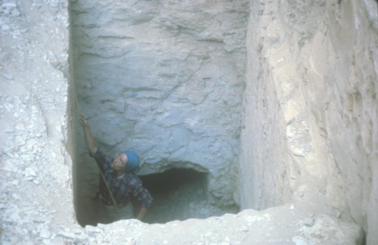
Next, the theodolite is set up on an arbitrary point inside the tomb and measurements are taken to the plumb bob tips (one of which is used as zero degrees). The horizontal position of the arbitrary set-up may be determined by using the azimuth measurements while the vertical position of the point may be determined by using the zenith measurements. (While only two sets of measurements are absolutely necessary, we usually use a third plumb bob as a check.)
If the shaft is irregular, intermediate measurements may be taken at one-meter (3.3 feet) intervals. The horizontal position of each corner can be fixed by measurements from at least two plumb bob strings. If there is more than one chamber within a shaft tomb, the mapping proceeds as with any other tomb.
This procedure provides information that is easily adapted for a computer and also allows for a high degree of accuracy when dealing with irregularly cut tombs. It does take a bit more time than other methods, however, because more measurements are necessary and these must be reduced trigonometrically to derive horizontal distances and elevations. Once data reduction is completed (an easy matter with modern calculators), the measurements are as easily used for a manual drawing as for a computer-generated drawing of the tomb.
During the initial Weld seasons of the Theban Mapping Project, when the majority of the tombs in the Valley of the Kings were mapped, measurements were recorded by hand. Angular measurements were read from the theodolite, and distances recorded with a steel measuring tape. Since then, the introduction of total stations (computerized theodolites) has simplified the surveying procedure. Angular measurements are read internally. For slope distances, a prism is held at each feature to be mapped and the Total Station's laser sighting measures the distance. All readings are stored electronically and data reduction is done automatically by the total station. The points mapped can then be downloaded directly to a computer as X, Y, and Z coordinates. The accessible parts of KV5 and KV10 were mapped in this fashion.
(Adapted from "Methods of Tomb Survey" by Catharine H. Roehrig; first published in Atlas of the Valley of the Kings, edited by Kent R. Weeks.)
Methods of Topographic Survey
What Is a Grid?
A surveying and mapping grid is a plane, rectangular mathematical matrix, usually oriented to the cardinal direction of north. A grid conforms to the curved surface of the earth, the geoid, usually at sea-level elevation. Thus, geodetic surveying, which considers the earth's curvature, is not required for working on a plane coordinate grid. A grid is anchored to the ground through survey monuments that are set in the ground and surveyed through conventional Weld survey techniques. Northing and easting values are arbitrarily assigned to a beginning control point, or they are derived from previously calculated and published tables for particular conformal mapping projections. The two most commonly used grids are the Lambert and the transverse Mercator. These grids, as projected onto the geoidal shape of the earth, comprise zones that are limited in west/east and south/north extent and that render the best plane surveying values.
Azimuth orientation of a grid is usually accomplished by occupying the control point of origin with a surveying instrument and making repeat angular observations between a circumpolar star, such as Polaris, and a second monumented control point. Thus, the derived azimuth is the basis for establishment of true north for the grid.
The Theban Mapping Project Grid
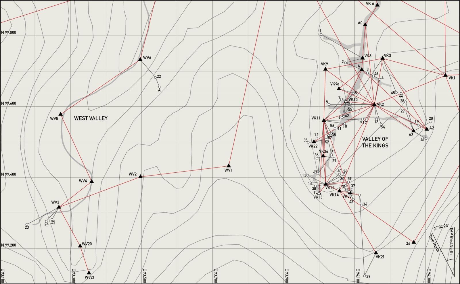
Eight sets of observations of Polaris were completed on the evening of 16 June, 1978 with the theodolite occupying traverse point 14 and turning angular directions from Polaris to traverse point 15. However, it was decided to adopt the monumental axis of Karnak Temple as a "true" west/east azimuth (90 degrees clockwise from north). The result is that the TMP Grid is oriented 27 degrees, 02 minutes, and 23 seconds clockwise from true north.
Traverse point 1 was arbitrarily assigned the values of North 100,000 meters (328,084 feet) and East 100,000 meters. These values were adopted to assure that negatives values would not enter into the grid. In addition, the Theban Necropolis was a considerable distance westerly, so there would not be any problem with confusing a northing value with one of easting, or vice versa.
The Control Traverse
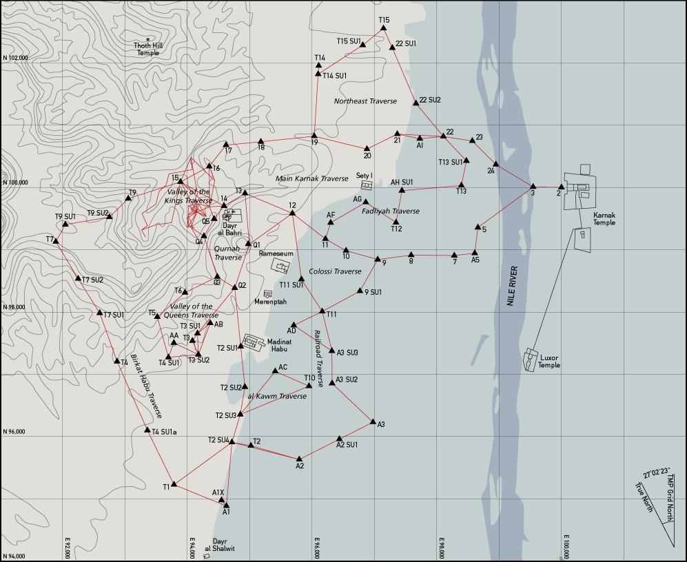
Traverse point 2 on the Karnak Temple baseline was first occupied by the theodolite. From there the survey began with a backsight on traverse point 1, which was around 400 meters (1,312 feet) easterly along the temple baseline and in the heart of the temple. Subsequently, measurements of distance and direction (angular - both horizontal and vertical) were made across the Nile, around the Valley of Kings, and back to the two points of beginning. This resulted in a 27- course (two more courses than desired), closed-loop traverse that was 13,809 meters long (45,305 feet).
After the initial traverse was completed, control points were established in the Valley of the Kings. These were then used to set out further control points at the entrances of all visible tombs, to be used in the surveys of the tombs themselves.
Measurements of Control Traverse
Distances of each course were measured with a Wild DI-10 Distomat, which had a range of plus or minus 1,000 meters, depending on atmospheric conditions and the number of reflector prisms used for a single measurement. The DI-10 used invisible infrared lightwave propagation to a distant precise reflector and thence back to the DI-10's receiver and processor module. Nominal accuracy was one centimeter. All lines measured were on a slope from the transmitter at the theodolite to the reflector. The longest course, necessitated by the terrain and Welds of sugar cane, was 800 meters (2,625 feet). A check line of 1,200 meters (3,937 feet) was measured across the middle of the closed loop.
In addition to measurements of horizontal directions, zenith angles were made along each course. These values were used in converting slope distances to horizontal values and in computing differences in elevation between the occupied station and the station being sighted. These horizontal values were further reduced to sea-level elevation, the datum where all coordinate values were calculated.
Standards of Accuracy Used
A standard of accuracy requires concomitant Weld procedures, which were followed as rigorously as possible under conditions imposed by weather and personnel. To assure adequate and proper control for mapping topographical and planimetric features, such as tombs and temples, the standards adopted were second-order (modified):
- Number of courses between azimuth checks: 25 or less.
- Azimuth closure not to exceed 3 sec/station.
- Position closure after azimuth adjustment: 1:10,000.
- Distance measurement accurate within 1:15,000.
- Minimum distance to be measured with DI-10: 200 m.
- Minimum number of direction observations with a one-second theodolite: 4 positions of circle.
- Differential leveling-loop closure not to exceed 0.008 m multiplied by the square root of the loop length in km.
Traverse Closure
The total length of the 27-course control traverse was 13,809 meters. Azimuth closure approximated 1.5 seconds per angle, or direction, measured. This error of closure yielded an accuracy of 1:65,000. This closure easily met our second-order (modified) standard. Such accuracy is more than adequate for ground control of aerial photography and for archaeological Weld mapping. All calculations and adjustments were made and adjusted as required by the use of a Hewlett Packard HP-97 with an HP surveying program card.
Vertical Control
Three Bench marks were recovered from the 1920s Survey of Egypt, proved for agreement, and adopted for elevation control. One of the three bench marks is only a couple of hundred meters from the house of Howard Carter. Another is embedded in the side of an alabaster factory in al Qurna.
Vertical Measurements
Elevations were determined by differential leveling and by trigonometric resolution of slope-distance measurements and zenith angles. Three-wire differential levels were run with a pendulum level. Each line was run ahead and back to form individual closed loops between each succeeding pair of turning points. In areas of marked relief, differences in elevation between traverse points were determined solely by trigonometric means.
Level rods were made from matched pairs of five-meter pocket tapes, which were affixed to wooden staffs. The four-meter level-rod staffs were made of wood that is similar to fir. Rod bubbles were essential for plumbing the rods in the typical desert winds. On two occasions, we were blown out by the force of the khamsin winds of late April. Iron livestock tether pins were used as turning pins and PK nails were used for "permanent" TPs.
Closures
All lines, both differential and trigonometric, were closed either in loops or upon other lines. The differential lines closed at second-order accuracies and the trigonometric lines closed within third-order values.
(Abridged and adapted from "Methods of Topographical Survey" by David A. Goodman; first published in Atlas of the Valley of the Kings, edited by Kent R. Weeks.)

